Vibration loads account for around 20 % of the causes of malfunctions in electronic assemblies in mobile applications. For example, engine controls in cars with drive-related mounting locations are subject to considerable and recurring vibration loads. Our customers require assemblies that are resistant and, at best, permanently resistant to the effects of vibration.
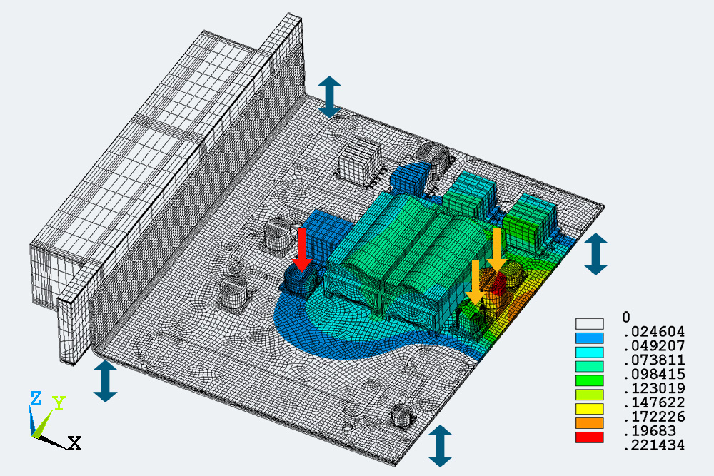
The occurrence of mechanical stresses in the solder contacts is caused by the transfer of vibration from the carrier vehicle (e.g., automobile) to the PCB. The dynamic forces are introduced via the fixings by screwing, gluing, or clamping. This results in a deflection of the PCB and a transfer of dynamic inertia forces to the high-mass electronic components. Both effects lead to mechanical stress in the connecting solder contacts. The transmission of forces is strongly dependent on the frequency of the vibrations. The vibration power is usually specified in the frequency domain as the power spectral density (PSD) and describes the vibration energy that is transmitted to the assembly in each frequency range. The dynamic forces are often direction dependent. The PSD function to be defined is specified using frequency-PSD value pairs. In the field of automotive assemblies, for example, frequency ranges up to 2 kHz are relevant.
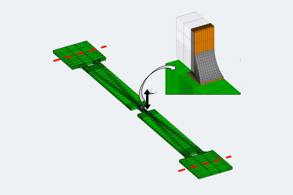
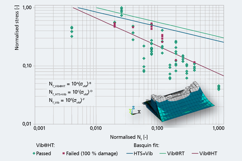
By means of simulation and targeted experimentation, service life correlations are created that allow service life predictions to be made for components. Furthermore, entire assemblies are simulated in the installation situation to carry out a hotspot analysis to identify the critically stressed components and thus optimize the overall design.


