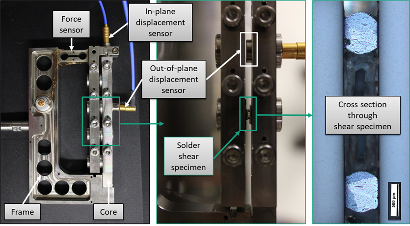
To support the industry's requirements for the reliability and service life design of electronic connections and materials in electronics, a new type of test method has been developed for fast and cost-effective evaluation. This system uses suitable sensors to record the mechanical deformation and the forces applied to the test specimen during exposure to a cyclically recurring temperature change load. The test specimen inserted into the load frame is heated or cooled homogeneously in a temperature cycling chamber. Due to the material-related expansion of the load frame material, a recurring thermo-mechanical load is introduced into the test specimen during the temperature change, which leads to a fatigue behavior to be characterized. Several load frames are used simultaneously to increase statistical reliability or to be able to perform the test under different loads. The test specimen load can essentially be varied by the position of the test specimen in the load frame and by the temperature profile. Furthermore, the geometry, the choice of material and the rigidity of the load frame and the test specimen can be changed.